A Rectangular Loop Of Wire With Sides Is Located
Holbox
Mar 20, 2025 · 6 min read
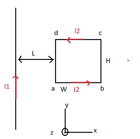
Table of Contents
A Rectangular Loop of Wire: Exploring Magnetic Fields and Induced Currents
A rectangular loop of wire, seemingly simple, offers a rich playground for exploring fundamental concepts in electromagnetism. Its behavior within a magnetic field, whether static or changing, reveals the intricate dance between electricity and magnetism, underpinning many technological marvels we take for granted today. This comprehensive article delves into the physics behind a rectangular loop of wire, examining its response to magnetic fields, the currents induced within it, and the applications stemming from these principles.
Understanding the Basics: Magnetic Flux and Faraday's Law
Before we delve into the specifics of a rectangular loop, let's establish the core principles governing its interaction with magnetic fields. The key concept is magnetic flux, a measure of the total magnetic field passing through a given area. It's calculated as the dot product of the magnetic field vector (B) and the area vector (A):
Φ = B • A = BA cos θ
Where θ is the angle between the magnetic field and the area vector (normal to the loop's surface). Crucially, the magnetic flux is not just about the strength of the magnetic field, but also the orientation of the loop within the field.
This brings us to Faraday's Law of Induction, a cornerstone of electromagnetism. It states that a changing magnetic flux through a loop of wire induces an electromotive force (EMF), which in turn drives a current in the loop. Mathematically:
EMF = -dΦ/dt
The negative sign reflects Lenz's Law, stating that the induced current creates a magnetic field that opposes the change in the original magnetic flux. This opposition ensures energy conservation.
Analyzing a Rectangular Loop in a Uniform Magnetic Field
Let's consider a rectangular loop of wire with sides of length 'a' and 'b', placed within a uniform magnetic field B.
Static Field: No Induced Current
If the magnetic field is constant and the loop is stationary, the magnetic flux through the loop remains unchanged. Consequently, dΦ/dt = 0, and there's no induced EMF or current. The loop simply sits passively within the field.
Changing Field: Induced Current
The situation changes dramatically if the magnetic field strength changes over time (dB/dt ≠ 0), or if the loop moves within a constant field, altering the angle θ and thus changing the flux.
Scenario 1: Changing Field Strength: If the magnetic field strength increases, the flux through the loop increases, inducing an EMF that drives a current. According to Lenz's Law, this induced current creates a magnetic field that opposes the increase in the original field. Similarly, a decreasing field induces a current that tries to maintain the original flux.
Scenario 2: Rotating Loop: Imagine the loop rotating within a constant magnetic field. As the loop rotates, the angle θ between the area vector and the magnetic field changes, causing the magnetic flux to fluctuate. This fluctuating flux induces an alternating EMF and current in the loop. The frequency of this alternating current is directly related to the rotational speed of the loop. This principle is fundamental to the operation of electric generators.
Scenario 3: Moving Loop: If the loop moves within a constant magnetic field, the area of the loop effectively "seen" by the field changes. This change in the effective area alters the magnetic flux, leading to an induced EMF and current. The direction of the induced current depends on the direction of the loop's motion relative to the field.
Calculating the Induced EMF and Current
Calculating the induced EMF and current requires careful consideration of the specific scenario. For a rectangular loop:
-
Uniform Field, Changing Strength: The induced EMF is simply: EMF = -A(dB/dt) where A = ab is the area of the loop.
-
Uniform Field, Rotating Loop: The induced EMF is more complex, involving trigonometric functions that account for the changing angle θ over time. The peak EMF is proportional to the product of the magnetic field strength, the area of the loop, and its angular velocity.
-
Uniform Field, Moving Loop: The induced EMF depends on the velocity of the loop and the component of the magnetic field perpendicular to the direction of motion.
In all cases, once the induced EMF is calculated, Ohm's Law can be used to determine the induced current: I = EMF/R, where R is the total resistance of the loop.
Applications of Rectangular Loops
The principles governing the behavior of a rectangular loop of wire have far-reaching applications in various technologies:
-
Electric Generators: As mentioned earlier, rotating a rectangular loop within a magnetic field is the basis for electric generators. These generators convert mechanical energy (rotation) into electrical energy.
-
Electric Motors: The reverse process – applying a current to a loop within a magnetic field to create rotation – is the core principle behind electric motors.
-
Transformers: Transformers utilize changing magnetic fields to induce currents in separate loops of wire, facilitating voltage transformations crucial for power distribution and electronic circuits.
-
Sensors: Changes in magnetic fields can be detected by monitoring the induced current in a rectangular loop, forming the basis for various magnetic field sensors used in numerous applications.
-
Wireless Power Transfer: Inductive coupling, based on the principle of mutual inductance between two loops, enables wireless power transfer.
Advanced Considerations
The analysis presented so far considers ideal scenarios. In real-world situations, several factors complicate the behavior of a rectangular loop:
-
Self-Inductance: The loop itself possesses self-inductance, meaning that a changing current in the loop induces a back EMF that opposes the change in current. This self-inductance affects the transient behavior of the loop and must be considered in dynamic analyses.
-
Resistance: The resistance of the wire affects the current flowing in the loop. A higher resistance reduces the magnitude of the induced current.
-
Non-uniform Fields: In many real-world applications, the magnetic field is not uniform. This requires more sophisticated mathematical techniques to calculate the magnetic flux and induced EMF.
-
Capacitance: The loop can possess capacitance, further complicating the dynamic response.
-
Eddy Currents: In scenarios involving conductive materials near the loop, eddy currents can be induced, affecting the overall behavior of the system.
Conclusion
The seemingly simple rectangular loop of wire provides a powerful tool for understanding the fundamentals of electromagnetism and its numerous applications. Its response to varying magnetic fields, whether static or dynamic, highlights the interconnectedness of electricity and magnetism. By grasping the principles governing its behavior, we can unlock the secrets behind a multitude of technologies that shape our modern world. The intricate interplay of magnetic flux, Faraday's Law, Lenz's Law, and circuit parameters provides an endlessly fascinating area of study, opening doors to further exploration in electromagnetism and its diverse applications. Further research can explore the loop's behavior in non-uniform fields, the impact of material properties, and its role in more complex electromechanical systems.
Latest Posts
Latest Posts
-
Add Solid Fill Red Data Bars To Range D4 D11
Mar 20, 2025
-
Choose The Best Lewis Structure For Ocl2
Mar 20, 2025
-
If The Ka Of A Monoprotic Weak Acid Is
Mar 20, 2025
-
Draw The Electron Configuration For A Neutral Atom Of Cobalt
Mar 20, 2025
-
Label The Parts Of A Gomphosis
Mar 20, 2025
Related Post
Thank you for visiting our website which covers about A Rectangular Loop Of Wire With Sides Is Located . We hope the information provided has been useful to you. Feel free to contact us if you have any questions or need further assistance. See you next time and don't miss to bookmark.
