Designers Typically Compare Circuit Sizes By
Holbox
Mar 15, 2025 · 6 min read
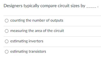
Table of Contents
Designers Typically Compare Circuit Sizes By: A Deep Dive into Area Optimization Techniques
Designing integrated circuits (ICs) is a complex balancing act. Performance, power consumption, and cost are all crucial factors, but they're often intertwined with another critical metric: circuit size. Minimizing circuit area isn't just about saving silicon; it directly impacts manufacturing costs, yield, and ultimately, the overall profitability of a chip. This article delves into the various ways designers compare circuit sizes, exploring the methodologies, tools, and considerations involved in this vital aspect of chip design.
Understanding the Metrics: Beyond Simple Area
While "circuit size" might seem straightforward – simply the physical area occupied by the circuit on the silicon die – the reality is much more nuanced. Designers rarely compare circuits using a single, simplistic metric. Instead, they utilize a multifaceted approach, considering various aspects of area optimization:
1. Total Area: The Big Picture
This is the most straightforward metric: the total area encompassed by the circuit's layout, typically measured in square micrometers (µm²) or square millimeters (mm²). Total area directly reflects the amount of silicon used and is a primary driver of manufacturing cost. However, solely focusing on total area can be misleading, as it doesn't account for the efficiency of the design.
2. Area Efficiency: Optimizing for Functionality
Area efficiency is a more insightful metric, comparing the circuit's functional area (the area directly contributing to the circuit's functionality) to its total area. A highly efficient circuit will have a minimal ratio of non-functional area (routing channels, unused space, etc.) to functional area. This is crucial for densely packed SoCs (Systems on a Chip) where every square micrometer counts.
3. Relative Area: Benchmarking Against Competitors or Previous Designs
Comparing the area of a new design to existing, similar circuits provides valuable context. This relative area is often expressed as a percentage or ratio, illustrating improvement or degradation compared to a baseline. This benchmark helps designers assess the effectiveness of their optimization strategies. For instance, a new design achieving a 15% area reduction compared to a previous generation is a significant achievement.
Comparing Circuit Sizes: Methods and Tools
The comparison of circuit sizes isn't a manual process. Designers leverage sophisticated Electronic Design Automation (EDA) tools and methodologies to perform accurate and efficient comparisons:
1. Layout Viewers and Analysis Tools
EDA suites provide dedicated layout viewers that allow designers to visually inspect the circuit layout, measure its dimensions, and analyze its area utilization. These tools often offer advanced features like area reporting, layer-specific area analysis, and density maps, providing granular insights into the circuit's spatial characteristics. These tools are crucial for identifying areas for optimization and visualizing the impact of design changes.
2. Design Rule Check (DRC) and Layout Versus Schematic (LVS)
DRC verifies that the layout adheres to the fabrication process's design rules, ensuring manufacturability. LVS compares the layout to the schematic to ensure that the physical implementation accurately reflects the intended functionality. Both DRC and LVS indirectly contribute to area comparison by identifying potential layout errors that could inflate the circuit's size or render it un-manufacturable. A clean DRC and LVS check ensures that the area reported is accurate and reflects a functional design.
3. Static Timing Analysis (STA) and its impact on Area
While not a direct area measurement tool, STA plays a critical role in area optimization. STA helps identify critical paths in the design that limit clock frequency. Addressing these timing violations often requires adding buffers or other logic elements, thus potentially increasing the circuit area. Therefore, STA results inform optimization decisions, balancing performance with area constraints. Successful STA means you can optimize for smaller areas without sacrificing speed and performance.
4. Power Analysis Tools
Power consumption is inherently linked to circuit area. Larger circuits generally consume more power. Power analysis tools help designers identify power-hungry components, enabling targeted optimization to reduce both power consumption and area. Tools like these provide a holistic view that helps designers optimize circuit area without compromising power efficiency.
5. Automated Placement and Routing Tools
Modern EDA tools incorporate advanced algorithms for automated placement and routing, crucial for minimizing circuit area. These tools leverage techniques like simulated annealing, genetic algorithms, and constraint-driven optimization to achieve compact layouts. The choice of placement and routing algorithms significantly affects the final circuit area. Comparing results from different tools or algorithms is common practice for optimization.
Advanced Techniques for Area Optimization
Beyond the basic tools and metrics, advanced techniques are employed to further minimize circuit area:
1. Standard Cell Libraries and Optimization
Utilizing optimized standard cell libraries is fundamental. These libraries contain pre-designed logic gates and other components optimized for area and performance, ensuring consistency and efficiency in the design. Choosing cells with minimal area for a given functionality reduces the overall circuit size.
2. Logic Optimization and Synthesis
Before layout, logic optimization techniques, such as Boolean minimization and technology mapping, reduce the complexity of the logic network, leading to smaller layouts. Synthesis tools transform the RTL (Register Transfer Level) design into a gate-level netlist, representing the circuit's logical structure. Efficient synthesis directly impacts the final area.
3. Floorplanning and Power Planning
Effective floorplanning strategically arranges major blocks within the circuit, minimizing interconnect lengths and improving routing efficiency. Power planning efficiently distributes power and ground lines, reducing the area consumed by power distribution networks. These strategic approaches impact the final area before detailed routing even begins.
4. Clock Tree Synthesis
The clock tree distributes the clock signal to all sequential elements. Efficient clock tree synthesis is vital to minimize skew and area. Skew—the difference in arrival times of the clock signal—can necessitate additional buffers or other components, increasing circuit area.
5. Advanced Routing Techniques
Advanced routing techniques, such as detailed routing algorithms, channel routing, and global routing, strive to optimize the routing resources and minimize the area consumed by interconnect wiring. These algorithms seek to minimize wire length and congestion, leading to more compact designs.
Beyond the Numbers: Considering Other Factors
While circuit area is a crucial metric, designers must also consider other factors that can influence their choices:
-
Performance: Reducing area sometimes comes at the expense of performance. Designers need to find the optimal balance between area and speed, often employing techniques like pipelining or clock gating to mitigate performance trade-offs.
-
Power Consumption: Smaller circuits generally consume less power, but optimization strategies might increase power in certain areas if not carefully managed. Careful analysis is crucial to ensure overall power reduction.
-
Testability: Design for testability (DFT) techniques can add area overhead, but they are essential for ensuring the functionality of the chip. Balancing testability needs with area optimization is critical.
-
Manufacturing Yield: Smaller circuits can sometimes lead to higher yields, as they are less susceptible to manufacturing variations. However, extremely dense designs can introduce other manufacturability challenges.
-
Cost: The total cost of manufacturing is influenced by area, yield, and test costs. Minimizing area is a major factor in reducing manufacturing costs, but it's not the sole contributor.
Conclusion: A Holistic Approach to Area Optimization
Comparing circuit sizes is a multifaceted process requiring a deep understanding of various metrics, tools, and techniques. Designers don't simply compare raw area figures but delve into area efficiency, relative area improvements, and the interplay between area and other critical parameters like performance, power, and cost. A holistic approach, integrating advanced optimization techniques and considering all relevant factors, is essential for achieving optimal circuit designs that balance size, performance, power, and cost-effectiveness. The ongoing evolution of EDA tools and design methodologies continues to push the boundaries of area optimization, enabling the creation of increasingly smaller, more efficient, and powerful integrated circuits.
Latest Posts
Latest Posts
-
Lysosomes Are Membrane Bound Vesicles That Arise From The
Mar 15, 2025
-
What Intoxications Signs Is John Showing
Mar 15, 2025
-
Common Mistakes Made When Managing Current Cash Needs Include
Mar 15, 2025
-
The Amount Of Current Assets Minus Current Liabilities Is Called
Mar 15, 2025
-
You Download Zoom For Your First Meeting
Mar 15, 2025
Related Post
Thank you for visiting our website which covers about Designers Typically Compare Circuit Sizes By . We hope the information provided has been useful to you. Feel free to contact us if you have any questions or need further assistance. See you next time and don't miss to bookmark.
