The Ammeter In The Figure Reads 3.0 A
Holbox
Mar 28, 2025 · 6 min read
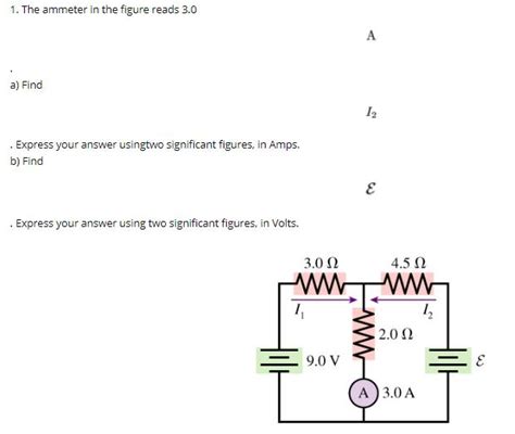
Table of Contents
- The Ammeter In The Figure Reads 3.0 A
- Table of Contents
- The Ammeter Reads 3.0A: Unraveling the Circuit's Secrets
- Understanding the Ammeter Reading
- The Importance of Circuit Diagrams
- Applying Ohm's Law and Kirchhoff's Laws
- Scenario 1: Simple Series Circuit
- Scenario 2: Simple Parallel Circuit
- Scenario 3: Complex Circuits with Multiple Components
- Practical Implications of a 3.0A Reading
- Beyond the 3.0A Reading: The Bigger Picture
- Safety Considerations
- Latest Posts
- Latest Posts
- Related Post
The Ammeter Reads 3.0A: Unraveling the Circuit's Secrets
An ammeter reading of 3.0A provides a crucial piece of information about a circuit, but it's far from the whole story. Understanding what this reading signifies requires a deep dive into circuit analysis, encompassing Ohm's Law, Kirchhoff's Laws, and the characteristics of different circuit components. This article will explore the implications of a 3.0A ammeter reading, providing a comprehensive guide to interpreting this data and drawing meaningful conclusions about the circuit's behavior.
Understanding the Ammeter Reading
A 3.0A ammeter reading directly indicates that 3.0 Coulombs of charge are passing a specific point in the circuit every second. This current flow is driven by a potential difference (voltage) and is constrained by the resistance within the circuit. The 3.0A value itself doesn't reveal the underlying causes; it's a consequence of the interplay between voltage and resistance. To understand the "why" behind the 3.0A reading, we need more information.
The Importance of Circuit Diagrams
Without a circuit diagram, interpreting a 3.0A ammeter reading is like trying to solve a puzzle with missing pieces. The diagram provides critical context:
- Component Identification: Knowing the type and values of components (resistors, capacitors, inductors, etc.) is essential. Different components affect current flow differently.
- Circuit Topology: The way components are connected (series, parallel, or a combination) significantly impacts the current distribution.
- Ammeter Placement: The location of the ammeter within the circuit determines which part of the circuit the 3.0A reading refers to. The current might be different in other parts of the circuit.
Let's assume we have a circuit diagram showing the ammeter reading 3.0A.
Applying Ohm's Law and Kirchhoff's Laws
Ohm's Law and Kirchhoff's Laws are fundamental principles in circuit analysis. They provide the mathematical tools to relate voltage, current, and resistance.
Ohm's Law: This states that the current (I) through a conductor between two points is directly proportional to the voltage (V) across the two points and inversely proportional to the resistance (R) between them. Mathematically: V = IR.
Kirchhoff's Current Law (KCL): The sum of currents entering a junction (node) in a circuit equals the sum of currents leaving that junction. This reflects the conservation of charge.
Kirchhoff's Voltage Law (KVL): The sum of all voltages around any closed loop in a circuit equals zero. This reflects the conservation of energy.
Let’s consider different scenarios where an ammeter reads 3.0A.
Scenario 1: Simple Series Circuit
Imagine a simple series circuit with a single resistor and a power source. If the ammeter, placed in series with the resistor, reads 3.0A, we can use Ohm's Law to determine the voltage across the resistor or the resistance itself if one is known.
-
Knowing the Resistance: If the resistor has a value of, say, 10 ohms, then applying Ohm's Law (V = IR): V = 3.0A * 10Ω = 30V. The voltage across the resistor (and the power source) is 30V.
-
Knowing the Voltage: Conversely, if the voltage across the resistor is known to be 15V, then the resistance can be calculated: R = V/I = 15V / 3.0A = 5Ω. The resistor has a resistance of 5 ohms.
Scenario 2: Simple Parallel Circuit
In a parallel circuit, the voltage across each branch is the same, but the current divides among the branches. Let's say we have two resistors in parallel, and the ammeter is placed in the main line before the branches. If it reads 3.0A, this is the total current supplied by the source. The individual branch currents will add up to 3.0A according to Kirchhoff's Current Law. To determine the individual branch currents, we'd need the resistance values of each resistor.
If we know the voltage across the parallel combination (which is the same across each resistor), we can calculate the current in each branch using Ohm's Law. For example, if the voltage is 12V and one branch has a 4Ω resistor, the current in that branch would be 3A (12V / 4Ω = 3A). The other branch would then have 0A, to satisfy Kirchhoff's Current Law. A more likely scenario would be that the 3A current splits between the two branches.
Scenario 3: Complex Circuits with Multiple Components
For more complex circuits involving multiple resistors, capacitors, inductors, and possibly even active components (transistors, operational amplifiers), the analysis becomes more intricate. We would typically employ techniques like:
- Mesh Analysis: Applying KVL to create a system of equations to solve for unknown currents.
- Nodal Analysis: Applying KCL to create a system of equations to solve for unknown node voltages.
- Superposition Theorem: Analyzing the effects of each source individually and then summing the results to find the overall response.
- Thevenin's Theorem and Norton's Theorem: Simplifying complex circuits into equivalent simpler circuits.
These advanced techniques require a strong understanding of circuit theory and often involve solving systems of simultaneous equations.
Practical Implications of a 3.0A Reading
The 3.0A reading has several practical implications:
-
Power Dissipation: Power (P) is calculated as P = IV. Knowing the current (3.0A) and the voltage across a component, we can determine the power dissipated by that component. Excessive power dissipation can lead to overheating and component failure. This highlights the importance of selecting components with appropriate power ratings.
-
Component Selection: The 3.0A reading influences the selection of appropriate components. Wires, connectors, switches, and fuses must be rated to handle at least this level of current to avoid safety hazards.
-
Circuit Protection: Fuses and circuit breakers are designed to protect circuits from overcurrent. A 3.0A reading indicates that the protective devices should be rated higher than 3.0A to allow normal operation while preventing damage from overcurrent situations.
-
Troubleshooting: If the 3.0A reading is unexpectedly high or low compared to the expected value, it points to a problem within the circuit. Troubleshooting techniques like voltage measurements at different points in the circuit can help identify the source of the discrepancy.
Beyond the 3.0A Reading: The Bigger Picture
The 3.0A ammeter reading is just one data point. Effective circuit analysis demands a holistic approach, encompassing:
- Complete Circuit Diagram: A clear, labeled diagram is essential.
- Component Specifications: Knowing the values and ratings of all components is crucial.
- Multiple Measurements: Taking measurements at various points in the circuit, including voltage measurements, provides a more comprehensive picture.
- Understanding the System: Considering the overall purpose and operation of the circuit helps interpret the data in context.
By integrating these aspects, the seemingly simple 3.0A reading transforms from a single number into a valuable key to understanding the workings of the entire electrical system.
Safety Considerations
Working with electrical circuits requires careful attention to safety. Always ensure that you are working with appropriately rated equipment, and follow proper safety procedures. If you are not comfortable working with electrical circuits, seek the assistance of a qualified electrician.
This comprehensive guide provides a foundation for understanding the implications of a 3.0A ammeter reading. By applying the principles of circuit analysis and employing systematic troubleshooting techniques, electrical engineers and technicians can effectively interpret this crucial piece of information to diagnose problems and optimize circuit performance. Remember to always prioritize safety when working with electricity.
Latest Posts
Latest Posts
-
Fill In The Blanks In Symbol Column Of The Table
Mar 31, 2025
-
To Maximize Profitability And Competitiveness Firms Must
Mar 31, 2025
-
Infer Geologic History From A New Mexico Outcrop
Mar 31, 2025
-
Reference Cell A1 From The Alpha Worksheet
Mar 31, 2025
-
The Probability Distribution Of Is Called A
Mar 31, 2025
Related Post
Thank you for visiting our website which covers about The Ammeter In The Figure Reads 3.0 A . We hope the information provided has been useful to you. Feel free to contact us if you have any questions or need further assistance. See you next time and don't miss to bookmark.
