Find The Current Through The 12 ω Resistor.
Holbox
Mar 19, 2025 · 6 min read
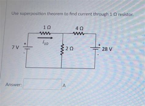
Table of Contents
Find the Current Through the 12 Ω Resistor: A Comprehensive Guide
Determining the current flowing through a specific resistor within a complex circuit can seem daunting, but with a systematic approach and a solid understanding of fundamental circuit principles, it becomes a manageable task. This article will guide you through various methods to find the current through a 12 Ω resistor, regardless of the circuit's complexity, using examples and explanations to solidify your understanding. We'll cover techniques applicable to both simple and more intricate circuits, equipping you with the tools to tackle a wide array of electrical engineering problems.
Understanding Basic Circuit Concepts
Before diving into specific methods, let's refresh some fundamental concepts:
Ohm's Law: The Cornerstone of Circuit Analysis
Ohm's Law forms the bedrock of circuit analysis. It states that the current (I) flowing through a resistor is directly proportional to the voltage (V) across it and inversely proportional to its resistance (R). Mathematically, this is represented as:
I = V / R
Where:
- I is the current in Amperes (A)
- V is the voltage in Volts (V)
- R is the resistance in Ohms (Ω)
Mastering Ohm's Law is crucial for successfully navigating any circuit analysis problem.
Kirchhoff's Laws: Navigating Complex Circuits
For circuits beyond simple series or parallel configurations, Kirchhoff's laws are indispensable. These laws provide a systematic way to analyze more complex circuit topologies.
-
Kirchhoff's Current Law (KCL): The sum of currents entering a node (junction) equals the sum of currents leaving that node. This principle reflects the conservation of charge.
-
Kirchhoff's Voltage Law (KVL): The sum of voltage drops around any closed loop in a circuit is zero. This principle reflects the conservation of energy.
Methods for Finding Current Through a 12 Ω Resistor
The approach to finding the current through the 12 Ω resistor depends heavily on the circuit's configuration. Let's explore different scenarios and the most effective solution methods:
1. Simple Series Circuit
In a simple series circuit, all components are connected end-to-end, forming a single path for current flow. The current is the same throughout the entire circuit.
Example: A 12 Ω resistor is connected in series with a 6 Ω resistor, and a 12V battery is connected across the combination.
Solution:
-
Find the total resistance: R<sub>total</sub> = R<sub>1</sub> + R<sub>2</sub> = 12 Ω + 6 Ω = 18 Ω
-
Apply Ohm's Law to find the total current: I<sub>total</sub> = V / R<sub>total</sub> = 12 V / 18 Ω = 0.67 A
-
Since it's a series circuit, the current through the 12 Ω resistor is the same as the total current: I<sub>12Ω</sub> = 0.67 A
2. Simple Parallel Circuit
In a simple parallel circuit, components are connected across each other, providing multiple paths for current flow. The voltage across each branch is the same, but the current divides among the branches.
Example: A 12 Ω resistor is connected in parallel with a 6 Ω resistor, and a 12V battery is connected across the combination.
Solution:
-
Calculate the equivalent resistance: 1/R<sub>total</sub> = 1/R<sub>1</sub> + 1/R<sub>2</sub> = 1/12 Ω + 1/6 Ω = 1/4 Ω. Therefore, R<sub>total</sub> = 4 Ω
-
Apply Ohm's Law to find the total current: I<sub>total</sub> = V / R<sub>total</sub> = 12 V / 4 Ω = 3 A
-
Apply Ohm's Law to find the current through the 12 Ω resistor: I<sub>12Ω</sub> = V / R<sub>12Ω</sub> = 12 V / 12 Ω = 1 A
3. Complex Circuits: Employing Kirchhoff's Laws and Other Techniques
For circuits with multiple loops and branches, applying Kirchhoff's Laws and other advanced techniques becomes necessary. These techniques may include:
-
Nodal Analysis: This method focuses on the nodes (junctions) in the circuit and applies KCL to solve for the node voltages. Once the node voltages are known, Ohm's Law can be used to calculate the current through any component.
-
Mesh Analysis: This method utilizes KVL to write equations for each loop (mesh) in the circuit. Solving these equations simultaneously allows you to determine the loop currents, from which the current through any component can be determined.
-
Superposition Theorem: This theorem simplifies complex circuits by analyzing the effect of each independent source individually and then summing the results to obtain the overall response.
-
Thevenin's Theorem and Norton's Theorem: These theorems allow you to simplify complex circuits into simpler equivalent circuits, making the analysis easier.
Example (using Nodal Analysis): Consider a circuit with a 12V battery, a 12 Ω resistor, a 6 Ω resistor, and a 4 Ω resistor forming a more complex arrangement.
Solution:
-
Choose reference node: Select a node as the reference (ground) node.
-
Define node voltages: Assign voltage variables (e.g., V<sub>1</sub>, V<sub>2</sub>) to the remaining nodes.
-
Apply KCL to each non-reference node: Write equations based on KCL, expressing the sum of currents entering and leaving each node in terms of the node voltages and resistances.
-
Solve the system of equations: Solve the simultaneous equations to find the values of the node voltages.
-
Apply Ohm's Law: Once the node voltages are known, use Ohm's Law to determine the current through the 12 Ω resistor using the voltage difference across it and its resistance.
Illustrative Example (simplified):
Let's assume after applying nodal analysis, you find that the voltage across the 12 Ω resistor (V<sub>12Ω</sub>) is 6V. Then, using Ohm's Law:
I<sub>12Ω</sub> = V<sub>12Ω</sub> / R<sub>12Ω</sub> = 6 V / 12 Ω = 0.5 A
Practical Considerations and Troubleshooting
-
Accurate Measurements: When dealing with real-world circuits, accurate measurements of voltage and resistance are paramount. Using a multimeter is essential for obtaining reliable data.
-
Component Tolerances: Keep in mind that resistors and other components have tolerances. These tolerances introduce small variations in actual values, affecting the calculated current.
-
Internal Resistance: Real-world voltage sources (batteries) have internal resistance, which can affect the circuit's behavior and should be considered in precise analyses.
-
Circuit Simulation Software: Software like LTSpice or Multisim can be invaluable for simulating circuits, verifying calculations, and visualizing the current flow.
Conclusion
Determining the current through a specific resistor, even in complex circuits, becomes achievable with a systematic application of fundamental circuit principles like Ohm's Law and Kirchhoff's Laws, combined with appropriate analysis techniques such as nodal analysis, mesh analysis, or theorem application. Remember to always start with a clear understanding of the circuit topology, and select the most appropriate method based on its complexity. Accurate measurements, consideration of component tolerances, and utilizing simulation software can significantly aid in achieving accurate and reliable results. Mastering these techniques will significantly improve your understanding and ability to analyze a wide range of electrical circuits.
Latest Posts
Latest Posts
-
What Do Sutures Gomphoses And Syndesmoses Have In Common
Mar 19, 2025
-
In Order To Promote Growth In Living Standards Policymakers Must
Mar 19, 2025
-
Suppose That A Small Town Wants To Install Street Lamps
Mar 19, 2025
-
What Is Something An Excellent Business Writer Would Do
Mar 19, 2025
-
Which Three Statements Describe A Dhcp Discover Message
Mar 19, 2025
Related Post
Thank you for visiting our website which covers about Find The Current Through The 12 ω Resistor. . We hope the information provided has been useful to you. Feel free to contact us if you have any questions or need further assistance. See you next time and don't miss to bookmark.
