Consider The Circuit Shown In Figure 1
Holbox
Mar 16, 2025 · 6 min read
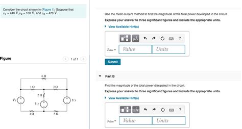
Table of Contents
- Consider The Circuit Shown In Figure 1
- Table of Contents
- Decoding Circuit Behavior: A Comprehensive Analysis of Figure 1 (Assume a Circuit Diagram is Provided)
- Fundamental Circuit Analysis Concepts: Setting the Stage
- 1. Kirchhoff's Laws: The Cornerstones of Circuit Analysis
- 2. Node Voltage Analysis: A Systematic Approach
- 3. Mesh Current Analysis: An Alternative Approach
- 4. Thevenin's Theorem and Norton's Theorem: Circuit Simplification
- Advanced Analysis Techniques and Applications
- Practical Applications and Real-World Scenarios
- Importance of Systematic Problem Solving
- Conclusion: Mastering Circuit Analysis for Success
- Latest Posts
- Latest Posts
- Related Post
Decoding Circuit Behavior: A Comprehensive Analysis of Figure 1 (Assume a Circuit Diagram is Provided)
This article delves into a comprehensive analysis of an unspecified circuit (Figure 1, assumed to be provided). Since the actual circuit diagram is missing, we will explore general circuit analysis techniques applicable to various circuit configurations. We will cover fundamental concepts like Kirchhoff's laws, node voltage analysis, mesh current analysis, Thevenin's theorem, and Norton's theorem. Understanding these principles will empower you to analyze any circuit, regardless of its complexity. We will also discuss the application of these techniques in practical scenarios and emphasize the importance of careful observation and systematic problem-solving.
Fundamental Circuit Analysis Concepts: Setting the Stage
Before diving into a specific analysis, let’s solidify our understanding of the fundamental principles that govern circuit behavior. These principles form the bedrock of any effective circuit analysis.
1. Kirchhoff's Laws: The Cornerstones of Circuit Analysis
Kirchhoff's Current Law (KCL): This law states that the algebraic sum of currents entering a node (a junction point in a circuit) is equal to zero. In simpler terms, the current entering a node must equal the current leaving the node. This principle is based on the conservation of charge – charge cannot accumulate at a node.
Kirchhoff's Voltage Law (KVL): This law states that the algebraic sum of voltages around any closed loop in a circuit is equal to zero. This principle is based on the conservation of energy – the energy gained in traversing a voltage source must be equal to the energy lost in traversing the circuit elements in a closed loop.
2. Node Voltage Analysis: A Systematic Approach
Node voltage analysis simplifies circuit analysis by focusing on the voltages at each node in the circuit. By applying KCL at each node and expressing the currents in terms of node voltages and resistances, a system of linear equations can be formed. Solving this system provides the node voltages, from which branch currents can be easily calculated.
Steps involved in Node Voltage Analysis:
- Identify the nodes: Clearly mark all the nodes in the circuit.
- Select a reference node: Choose one node as the reference node (usually the node connected to ground).
- Assign node voltages: Assign voltage variables (e.g., V1, V2, V3) to the remaining nodes with respect to the reference node.
- Apply KCL at each node: Apply KCL to each non-reference node, expressing the currents in terms of node voltages and resistances using Ohm's law (I = V/R).
- Solve the system of equations: Solve the resulting system of linear equations to find the node voltages.
- Calculate branch currents: Once the node voltages are known, calculate the branch currents using Ohm's law.
3. Mesh Current Analysis: An Alternative Approach
Mesh current analysis uses loop currents to analyze circuits. A mesh is a closed loop in the circuit. In this method, we assume currents flowing in each mesh and then apply KVL to each mesh to obtain a system of linear equations. Solving this system provides the mesh currents, from which branch currents and node voltages can be determined.
Steps involved in Mesh Current Analysis:
- Identify the meshes: Clearly mark each mesh in the circuit.
- Assign mesh currents: Assign current variables (e.g., I1, I2, I3) to each mesh, assuming a direction for each current.
- Apply KVL to each mesh: Apply KVL to each mesh, expressing the voltages across the elements in terms of mesh currents and resistances. Remember that a resistor shared by two meshes has currents from both meshes flowing through it.
- Solve the system of equations: Solve the resulting system of linear equations to find the mesh currents.
- Calculate branch currents and node voltages: Once the mesh currents are known, calculate branch currents by summing the mesh currents flowing through each branch. Node voltages can then be calculated using Ohm's law.
4. Thevenin's Theorem and Norton's Theorem: Circuit Simplification
These theorems provide powerful methods for simplifying complex circuits. They allow us to replace a complex network with a simpler equivalent circuit consisting of a voltage source (Thevenin) or a current source (Norton) in series/parallel with a single resistor.
Thevenin's Theorem: Any linear circuit can be replaced by an equivalent circuit consisting of a single voltage source (Vth) in series with a single resistor (Rth). Vth is the open-circuit voltage at the terminals, and Rth is the equivalent resistance looking into the terminals with all sources replaced by their internal resistances.
Norton's Theorem: Any linear circuit can be replaced by an equivalent circuit consisting of a single current source (In) in parallel with a single resistor (Rn). In is the short-circuit current at the terminals, and Rn is the same equivalent resistance as in Thevenin's theorem.
Advanced Analysis Techniques and Applications
Beyond the fundamental techniques, several advanced approaches exist for tackling complex circuits. These include:
- Superposition Theorem: This principle allows us to analyze circuits with multiple independent sources by considering the effect of each source individually and then summing the results.
- Source Transformation: This technique allows us to convert voltage sources to current sources and vice-versa, making circuit analysis simpler in certain cases.
- Delta-Wye Transformation: This transformation facilitates the simplification of circuits containing delta (triangle) or wye (star) connected resistors.
- Operational Amplifier (Op-Amp) Circuit Analysis: Op-amps are widely used in electronic circuits, and their analysis involves understanding their ideal characteristics and the application of virtual short circuit and open circuit concepts.
Practical Applications and Real-World Scenarios
Circuit analysis techniques are crucial in various fields:
- Electronics Design: Designing electronic circuits requires accurate analysis to ensure proper functionality and performance.
- Power Systems Engineering: Analyzing power grids and electrical distribution systems relies heavily on circuit analysis methods.
- Telecommunications: Designing and troubleshooting communication networks involves analyzing complex circuits.
- Control Systems: Analyzing control systems necessitates understanding the behavior of circuits and their interaction with other components.
Importance of Systematic Problem Solving
Analyzing circuits effectively requires a systematic approach:
- Clearly Define the Problem: Understand what you need to find (voltages, currents, power).
- Draw a Neat Circuit Diagram: A clear diagram is crucial for understanding the circuit's topology.
- Choose an Appropriate Analysis Method: Select the most efficient technique based on the circuit's complexity and the desired results.
- Solve the Equations Carefully: Accuracy is vital in circuit analysis.
- Verify Your Results: Check your answers using alternative methods or by verifying the fundamental principles (KCL and KVL).
Conclusion: Mastering Circuit Analysis for Success
This comprehensive exploration of circuit analysis techniques provides a solid foundation for understanding and analyzing various circuit configurations. By mastering these techniques and adopting a systematic approach to problem-solving, you will be well-equipped to tackle a wide range of circuit analysis challenges. Remember that practice is key to mastering these concepts, so work through various example problems to solidify your understanding. The ability to analyze circuits effectively is paramount in many engineering and scientific disciplines, paving the way for innovation and advancement in technology. Further exploration into specific circuit types and advanced techniques will significantly broaden your expertise in this crucial field. Continue to build your knowledge, and you'll find the seemingly complex world of circuit analysis becoming increasingly accessible and rewarding.
Latest Posts
Latest Posts
-
Secretin Stimulates The To Secrete
Mar 17, 2025
-
What Is The Identity Of Element X From Part B
Mar 17, 2025
-
A Resident On Transmission Based Precautions Must Be
Mar 17, 2025
-
Sarah Is A Scientist At A Cleared Defense Contractor
Mar 17, 2025
-
Accounting For Governmental And Nonprofit Entities
Mar 17, 2025
Related Post
Thank you for visiting our website which covers about Consider The Circuit Shown In Figure 1 . We hope the information provided has been useful to you. Feel free to contact us if you have any questions or need further assistance. See you next time and don't miss to bookmark.
