A Circuit Is Constructed With Six Resistors And Two Batteries
Holbox
Mar 16, 2025 · 7 min read
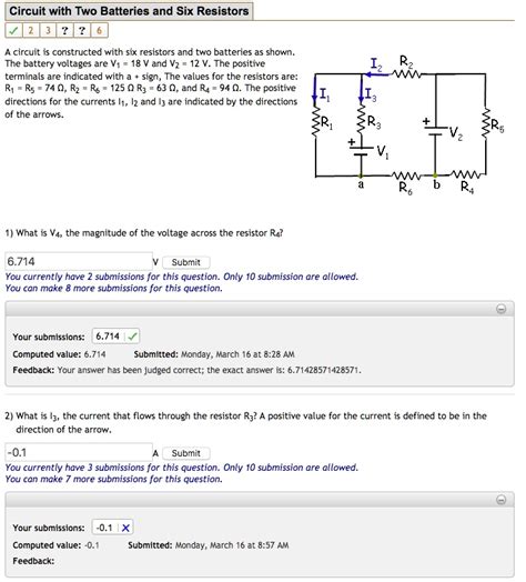
Table of Contents
A Circuit Constructed with Six Resistors and Two Batteries: A Deep Dive into Analysis and Design
Analyzing and designing circuits with multiple resistors and batteries requires a solid understanding of fundamental circuit principles. This comprehensive guide delves into the intricacies of a circuit incorporating six resistors and two batteries, providing a step-by-step approach to analysis, common configurations, and practical considerations. We will explore various methods for solving such circuits, highlighting their strengths and weaknesses.
Understanding Basic Circuit Concepts
Before tackling the complexities of our six-resistor, two-battery circuit, let's refresh some essential concepts:
Ohm's Law: The Foundation of Circuit Analysis
Ohm's Law, arguably the most fundamental principle in circuit analysis, states that the voltage (V) across a resistor is directly proportional to the current (I) flowing through it and its resistance (R). Mathematically, this is represented as:
V = I * R
This simple equation allows us to calculate any of the three parameters if the other two are known.
Kirchhoff's Laws: Navigating Complex Circuits
For circuits more complex than a single resistor, we rely on Kirchhoff's laws:
-
Kirchhoff's Current Law (KCL): The sum of currents entering a node (junction) equals the sum of currents leaving that node. This reflects the principle of charge conservation.
-
Kirchhoff's Voltage Law (KVL): The sum of voltage drops around any closed loop in a circuit equals zero. This reflects the principle of energy conservation.
These laws are crucial for systematically analyzing circuits with multiple branches and loops.
Analyzing a Six-Resistor, Two-Battery Circuit
Let's consider a specific example. Imagine a circuit with two batteries, each with a distinct voltage (e.g., V1 and V2), connected to a network of six resistors (R1 to R6). The arrangement of these components significantly affects the overall circuit behavior. We'll explore a few common configurations:
Series and Parallel Combinations
The simplest scenarios involve series and parallel combinations of resistors.
-
Series Connection: Resistors are connected end-to-end. The total resistance (Rs) is the sum of individual resistances: Rs = R1 + R2 + R3 + ...
-
Parallel Connection: Resistors are connected at both ends. The reciprocal of the total resistance (Rp) is the sum of the reciprocals of individual resistances: 1/Rp = 1/R1 + 1/R2 + 1/R3 + ...
If our six resistors are arranged solely in series or parallel, the analysis is relatively straightforward using Ohm's Law and the above formulas to find the equivalent resistance, followed by the calculation of the current and voltage drops across each resistor.
More Complex Arrangements: Mesh and Nodal Analysis
When resistors are connected in a more complex arrangement—not purely series or parallel—we need more advanced techniques:
-
Mesh Analysis: This method uses KVL to write equations for each independent loop (mesh) in the circuit. The resulting system of equations can be solved to find the loop currents. From these currents, we can determine the current through each resistor and subsequently the voltage drops.
-
Nodal Analysis: This method uses KCL to write equations for each independent node in the circuit. The resulting system of equations can be solved to find the node voltages. From these voltages, we can determine the voltage across each resistor and subsequently the current through each resistor.
Example Circuit Analysis using Mesh Analysis
Let's assume our six resistors (R1-R6) form a bridge circuit configuration with the two batteries (V1, V2) connected at appropriate points. To analyze this using mesh analysis:
-
Identify the Meshes: Define independent loops in the circuit. A bridge circuit generally has three meshes.
-
Assign Loop Currents: Assign a current (e.g., I1, I2, I3) to each mesh, assuming a direction for the current flow.
-
Apply KVL to Each Mesh: Write an equation for each mesh using KVL, expressing the voltage drops across each resistor in terms of the assigned loop currents and the battery voltages. For example, for mesh 1: V1 - R1I1 - R2(I1-I2) = 0.
-
Solve the System of Equations: Solve the resulting system of three equations with three unknowns (I1, I2, I3) using techniques like substitution, elimination, or matrix methods.
-
Calculate Resistor Currents and Voltage Drops: Use the obtained loop currents to find the current through each resistor and then calculate the voltage drops using Ohm's law.
Example Circuit Analysis using Nodal Analysis
Alternatively, we can use nodal analysis:
-
Identify the Nodes: Identify the independent nodes in the circuit. A bridge circuit often has four nodes.
-
Select a Reference Node: Choose one node as the reference node (ground), and assign voltages (e.g., V1, V2, V3) to the other nodes relative to the reference node.
-
Apply KCL to Each Node (Except the Reference Node): Write an equation for each non-reference node using KCL, expressing the currents entering or leaving the node in terms of the node voltages and resistor values. For example, for node 1: (V1 - V2)/R1 + (V1 - V3)/R2 - (V1 - V_battery)/R_battery = 0.
-
Solve the System of Equations: Solve the resulting system of equations to find the node voltages.
-
Calculate Resistor Currents and Voltage Drops: Use the node voltages to calculate the voltage across each resistor, then apply Ohm's Law to find the current through each resistor.
Both mesh and nodal analysis provide systematic approaches for solving complex circuits. The choice between them often depends on personal preference and the specific circuit configuration. Nodal analysis is generally preferred when there are fewer nodes than meshes.
Superposition Theorem: Handling Multiple Sources
When dealing with multiple voltage sources (like our two batteries), the superposition theorem offers a powerful simplification. This theorem states that the response (current or voltage) in any branch of a linear circuit containing multiple independent sources is the algebraic sum of the responses caused by each independent source acting alone, with all other independent sources replaced by their internal resistances.
To apply superposition:
-
Consider each source independently: Deactivate all sources except one (replace voltage sources with short circuits and current sources with open circuits).
-
Calculate the response: Calculate the voltage or current of interest with only the active source.
-
Repeat for each source: Repeat steps 1 and 2 for each independent source.
-
Sum the responses: Algebraically sum the individual responses to get the total response.
Practical Considerations and Circuit Design
The analysis methods discussed above provide a framework for understanding the behavior of a six-resistor, two-battery circuit. However, several practical factors influence the design and operation of such circuits:
-
Tolerance of Resistors: Real-world resistors have tolerances (e.g., ±5%, ±1%). This variation can affect the actual circuit behavior, potentially leading to deviations from the calculated values.
-
Internal Resistance of Batteries: Batteries possess internal resistance, which can influence the voltage available to the circuit, especially under heavy load.
-
Power Dissipation: Resistors dissipate power (P = I²R or P = V²/R). It’s crucial to select resistors with appropriate power ratings to avoid overheating or damage.
-
Circuit Protection: Fuses or circuit breakers may be necessary to protect the circuit from overcurrent conditions.
Advanced Techniques and Simulations
For exceptionally complex circuits, more advanced techniques like the Thevenin and Norton theorems can simplify the analysis. These theorems allow us to represent a complex circuit as a simpler equivalent circuit.
Furthermore, circuit simulation software (e.g., LTSpice, Multisim) provides invaluable tools for verifying circuit designs, analyzing performance, and exploring various "what-if" scenarios before physical implementation. Simulations allow you to quickly test different resistor values and battery voltages to see how the circuit responds, optimizing the design for desired behavior.
Conclusion
Analyzing a circuit with six resistors and two batteries requires a firm grasp of fundamental circuit laws and analysis techniques. This guide provided a detailed explanation of the common methods – series/parallel simplification, mesh analysis, nodal analysis, and superposition – equipping you with the knowledge to tackle such circuits effectively. Remember to consider practical aspects like resistor tolerance, battery internal resistance, power dissipation, and circuit protection during the design process. By combining theoretical understanding with practical considerations and, where appropriate, circuit simulation, you can successfully design and analyze intricate electrical circuits.
Latest Posts
Latest Posts
-
When Preparing To Begin A Speech Positive Nervousness Refers To
Mar 17, 2025
-
An Increase In Income Will Blank
Mar 17, 2025
-
Management Is Defined As The Pursuit Of Organizational Goals
Mar 17, 2025
-
Specialization In Production Is Economically Beneficial Primarily Because It
Mar 17, 2025
-
Movement That Tips The Soles Laterally
Mar 17, 2025
Related Post
Thank you for visiting our website which covers about A Circuit Is Constructed With Six Resistors And Two Batteries . We hope the information provided has been useful to you. Feel free to contact us if you have any questions or need further assistance. See you next time and don't miss to bookmark.
