A Circuit Is Constructed With 5 Capacitors And A Battery
Holbox
Mar 14, 2025 · 6 min read
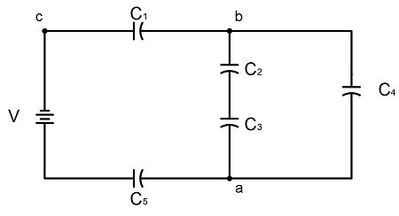
Table of Contents
A Circuit Constructed with 5 Capacitors and a Battery: Exploring Series, Parallel, and Series-Parallel Configurations
Building circuits with capacitors and a battery opens up a fascinating world of electrical behavior. Capacitors, unlike resistors, don't simply impede the flow of current; they store electrical energy in an electric field. The arrangement of capacitors within a circuit significantly impacts the overall capacitance and how the circuit responds to the battery's voltage. This article delves into the intricacies of circuits involving five capacitors and a battery, exploring different configurations and their resulting characteristics. We will analyze series, parallel, and series-parallel combinations, providing a comprehensive understanding of how to calculate equivalent capacitance and voltage distribution across each capacitor.
Understanding Basic Capacitor Behavior
Before diving into complex configurations, it's crucial to grasp fundamental capacitor principles. A capacitor is a passive two-terminal electrical component that stores energy electrostatically in an electric field. Its ability to store charge is quantified by its capacitance (C), measured in Farads (F). Capacitance depends on the physical characteristics of the capacitor – specifically, the area of the plates (A), the distance between them (d), and the dielectric constant (κ) of the material separating the plates:
C = κε₀A/d
where ε₀ is the permittivity of free space.
A key characteristic of capacitors is their ability to oppose changes in voltage. When a voltage is applied across a capacitor, it charges, accumulating charge on its plates until the voltage across it equals the applied voltage. The charging process isn't instantaneous; it follows an exponential curve. The time constant (τ), which describes the rate of charging and discharging, is given by:
τ = RC
where R is the resistance in the circuit.
Series Capacitor Configurations
In a series configuration, capacitors are connected end-to-end, forming a single path for current flow. The charge on each capacitor in a series circuit is the same, but the voltage across each capacitor is different and depends on its individual capacitance. The equivalent capacitance (C<sub>eq</sub>) for a series combination of n capacitors is calculated using the following formula:
1/C<sub>eq</sub> = 1/C₁ + 1/C₂ + 1/C₃ + ... + 1/Cₙ
For a circuit with five capacitors (C₁, C₂, C₃, C₄, C₅) in series, the equivalent capacitance would be:
1/C<sub>eq</sub> = 1/C₁ + 1/C₂ + 1/C₃ + 1/C₄ + 1/C₅
The total voltage (V<sub>total</sub>) applied by the battery is divided among the capacitors according to their individual capacitances:
V<sub>total</sub> = V₁ + V₂ + V₃ + V₄ + V₅
where Vᵢ represents the voltage across capacitor Cᵢ. The voltage across each capacitor is inversely proportional to its capacitance. Larger capacitors will have a smaller voltage drop.
Example: Series Circuit Analysis
Let's consider a circuit with five capacitors of values 1µF, 2µF, 3µF, 4µF, and 5µF connected in series with a 10V battery. The equivalent capacitance is:
1/C<sub>eq</sub> = 1/1 + 1/2 + 1/3 + 1/4 + 1/5 ≈ 2.283
C<sub>eq</sub> ≈ 0.438µF
The total charge (Q) stored in the circuit is:
Q = C<sub>eq</sub>V<sub>total</sub> = 0.438µF * 10V ≈ 4.38µC
Since the charge is the same on each capacitor, the voltage across each capacitor can be calculated:
- V₁ = Q/C₁ = 4.38µC/1µF ≈ 4.38V
- V₂ = Q/C₂ = 4.38µC/2µF ≈ 2.19V
- V₃ = Q/C₃ = 4.38µC/3µF ≈ 1.46V
- V₄ = Q/C₄ = 4.38µC/4µF ≈ 1.095V
- V₅ = Q/C₅ = 4.38µC/5µF ≈ 0.876V
Parallel Capacitor Configurations
In a parallel configuration, capacitors are connected across each other, providing multiple paths for current flow. The voltage across each capacitor in a parallel circuit is the same (equal to the battery voltage), but the charge on each capacitor is different and depends on its individual capacitance. The equivalent capacitance (C<sub>eq</sub>) for a parallel combination of n capacitors is simply the sum of the individual capacitances:
C<sub>eq</sub> = C₁ + C₂ + C₃ + ... + Cₙ
For a circuit with five capacitors in parallel, the equivalent capacitance is:
C<sub>eq</sub> = C₁ + C₂ + C₃ + C₄ + C₅
Example: Parallel Circuit Analysis
Using the same capacitor values (1µF, 2µF, 3µF, 4µF, 5µF) with a 10V battery, the equivalent capacitance is:
C<sub>eq</sub> = 1µF + 2µF + 3µF + 4µF + 5µF = 15µF
The total charge stored is:
Q<sub>total</sub> = C<sub>eq</sub>V<sub>total</sub> = 15µF * 10V = 150µC
The charge on each capacitor is:
- Q₁ = C₁V<sub>total</sub> = 1µF * 10V = 10µC
- Q₂ = C₂V<sub>total</sub> = 2µF * 10V = 20µC
- Q₃ = C₃V<sub>total</sub> = 3µF * 10V = 30µC
- Q₄ = C₄V<sub>total</sub> = 4µF * 10V = 40µC
- Q₅ = C₅V<sub>total</sub> = 5µF * 10V = 50µC
Series-Parallel Capacitor Configurations
Series-parallel combinations present a more complex scenario, requiring a step-by-step approach to determine the equivalent capacitance. You must simplify the circuit by first calculating the equivalent capacitance of series or parallel branches before combining them further.
Example: Series-Parallel Circuit Analysis
Consider a circuit with three capacitors (C₁, C₂, C₃) connected in parallel, and this parallel combination is then connected in series with two more capacitors (C₄, C₅).
-
First, find the equivalent capacitance (C<sub>parallel</sub>) of the parallel branch:
C<sub>parallel</sub> = C₁ + C₂ + C₃
-
Next, treat C<sub>parallel</sub> as a single capacitor in series with C₄ and C₅:
1/C<sub>eq</sub> = 1/C<sub>parallel</sub> + 1/C₄ + 1/C₅
Solve for C<sub>eq</sub>.
This approach allows you to systematically reduce the circuit to a single equivalent capacitor, simplifying the analysis of voltage and charge distribution. The voltage division will be different in each part of the circuit. The voltage across the parallel combination will be different from the voltage across the series combination, and the voltage will be further divided among capacitors in each combination based on their capacitance values.
Applications of Capacitor Circuits
Circuits with multiple capacitors have numerous applications across various fields:
-
Energy Storage: Capacitor banks are used in power systems for energy storage, smoothing out voltage fluctuations, and providing backup power.
-
Filtering: Capacitors are integral components in filters used to separate different frequency components of signals in audio, communication, and power electronics.
-
Timing Circuits: The charging and discharging characteristics of capacitors are used in timing circuits for generating precise time delays, such as in pulse generators and oscillators.
-
Coupling and Decoupling: Capacitors are employed to couple or decouple signals in circuits, blocking DC while allowing AC to pass.
-
Sensor Systems: Many sensor systems utilize capacitors to measure changes in physical parameters such as displacement, pressure, and humidity.
Advanced Considerations
The analysis presented above assumes ideal capacitors. In real-world scenarios, factors like capacitor tolerance, parasitic capacitance, and dielectric loss need to be considered. Parasitic capacitance, stemming from unintended capacitance between circuit elements, can affect the overall circuit performance, particularly at higher frequencies.
Conclusion
Understanding the behavior of capacitor circuits is essential for designing and analyzing various electronic systems. This article explored series, parallel, and series-parallel configurations of five capacitors with a battery, providing detailed analysis techniques for determining equivalent capacitance, voltage distribution, and charge storage. By mastering these fundamental concepts, you can confidently tackle more complex circuit designs and applications, leading to a deeper understanding of electrical engineering principles. Remember to always consider practical aspects such as component tolerance and parasitic effects for accurate circuit modeling and optimal performance.
Latest Posts
Latest Posts
-
Draw The Product Of The Reaction
Mar 14, 2025
-
All Of The Following Are Disadvantages Of A Corporation Except
Mar 14, 2025
-
Planning Value If Range Is Givn
Mar 14, 2025
-
All Of The Following Are True Except
Mar 14, 2025
-
Manufacturing Costs Include Direct Materials Direct Labor And
Mar 14, 2025
Related Post
Thank you for visiting our website which covers about A Circuit Is Constructed With 5 Capacitors And A Battery . We hope the information provided has been useful to you. Feel free to contact us if you have any questions or need further assistance. See you next time and don't miss to bookmark.
