You Have Two Capacitors One With Capacitance
Holbox
Mar 14, 2025 · 6 min read
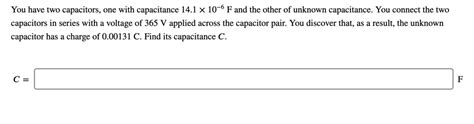
Table of Contents
Decoding Capacitor Behavior: Exploring Parallel and Series Configurations with Two Capacitors
Understanding how capacitors behave, particularly when arranged in parallel or series, is fundamental to electronics. This in-depth article delves into the intricacies of capacitor networks, focusing on the scenario where you have two capacitors with differing capacitances. We'll explore the resulting equivalent capacitance, voltage division, and energy storage, providing practical examples and calculations to solidify your understanding.
What is Capacitance?
Before diving into complex configurations, let's refresh our understanding of capacitance. Capacitance (C) is the ability of a capacitor to store electrical energy in the form of an electric field. It's measured in farads (F), although microfarads (µF), nanofarads (nF), and picofarads (pF) are more commonly used in practice. A capacitor essentially consists of two conductive plates separated by an insulating material called a dielectric. The capacitance is directly proportional to the area of the plates and the dielectric constant, and inversely proportional to the distance between the plates.
Formula: C = εA/d
Where:
- C = Capacitance
- ε = Permittivity of the dielectric material
- A = Area of the plates
- d = Distance between the plates
This simple formula highlights the key factors influencing a capacitor's ability to store charge.
Capacitors in Parallel
When two or more capacitors are connected in parallel, their positive terminals are connected together, and their negative terminals are connected together. In this configuration, the voltage across each capacitor is the same, but the total charge stored is the sum of the charges stored on each individual capacitor. The equivalent capacitance (Ceq) of parallel capacitors is simply the sum of the individual capacitances.
Formula: Ceq (parallel) = C1 + C2 + C3 + ...
Let's consider a practical example:
Example 1: Parallel Capacitors
Suppose we have two capacitors: C1 = 10 µF and C2 = 20 µF connected in parallel. The equivalent capacitance is:
Ceq = C1 + C2 = 10 µF + 20 µF = 30 µF
The equivalent capacitance is greater than either individual capacitance. This is because the parallel configuration effectively increases the total plate area available for charge storage.
Capacitors in Series
When capacitors are connected in series, their positive terminal of one capacitor is connected to the negative terminal of the next. In this arrangement, the charge on each capacitor is the same, but the voltage across each capacitor is different. The reciprocal of the equivalent capacitance is the sum of the reciprocals of the individual capacitances.
Formula: 1/Ceq (series) = 1/C1 + 1/C2 + 1/C3 + ...
Example 2: Series Capacitors
Let's use the same capacitors from Example 1, but now connected in series: C1 = 10 µF and C2 = 20 µF.
1/Ceq = 1/C1 + 1/C2 = 1/10 µF + 1/20 µF = (2 + 1)/20 µF = 3/20 µF
Therefore, Ceq = 20 µF/3 ≈ 6.67 µF
Notice that the equivalent capacitance in series is less than the smallest individual capacitance. This is because the series configuration effectively increases the distance between the plates, reducing the overall charge storage capacity.
Voltage Division in Series Capacitors
In a series capacitor network, the voltage across each capacitor is inversely proportional to its capacitance. This is known as voltage division. The voltage across each capacitor can be calculated using the following formulas:
- V1 = (C2 / (C1 + C2)) * Vtotal
- V2 = (C1 / (C1 + C2)) * Vtotal
Where:
- V1 = Voltage across capacitor C1
- V2 = Voltage across capacitor C2
- Vtotal = Total voltage applied across the series combination
Example 3: Voltage Division
Let's assume a total voltage of 12V is applied across the series combination of C1 (10 µF) and C2 (20 µF) from Example 2.
V1 = (20 µF / (10 µF + 20 µF)) * 12V = (2/3) * 12V = 8V
V2 = (10 µF / (10 µF + 20 µF)) * 12V = (1/3) * 12V = 4V
The larger capacitor (C2) has a smaller voltage across it, and vice-versa. The sum of the individual voltages (V1 + V2) always equals the total applied voltage.
Energy Stored in Capacitors
The energy (E) stored in a capacitor is given by the following formula:
Formula: E = 1/2 * C * V²
Where:
- E = Energy stored (in Joules)
- C = Capacitance (in Farads)
- V = Voltage across the capacitor (in Volts)
The total energy stored in a capacitor network is the sum of the energy stored in each individual capacitor. However, it's important to note that energy is not always conserved when capacitors are reconfigured. For example, if you charge capacitors individually and then connect them in parallel, energy will be dissipated as heat due to the redistribution of charge.
Example 4: Energy Storage
Let's calculate the energy stored in each capacitor from Example 3:
E1 = 1/2 * 10 µF * (8V)² = 320 µJ
E2 = 1/2 * 20 µF * (4V)² = 160 µJ
Total energy stored = E1 + E2 = 480 µJ
Practical Applications
Understanding capacitor behavior in parallel and series configurations is crucial in various applications, including:
-
Filtering: Capacitors are used extensively in filter circuits to block DC signals while allowing AC signals to pass. Series and parallel combinations are used to design different types of filters, such as high-pass, low-pass, and band-pass filters.
-
Energy Storage: Capacitor banks are used in power supplies to smooth out voltage fluctuations and provide a stable DC voltage. Large capacitor banks are also used in pulsed power applications, where high energy is required for short durations.
-
Timing Circuits: RC (Resistor-Capacitor) circuits are used in timing applications, such as oscillators and timers. The time constant of an RC circuit depends on the values of the resistor and capacitor, and the series or parallel configuration affects the overall time constant.
-
Coupling and Decoupling: Capacitors are used to couple or decouple signals in various circuits. For instance, coupling capacitors are used to block DC signals while passing AC signals between stages of an amplifier. Decoupling capacitors are used to bypass high-frequency noise signals to ground.
Troubleshooting Capacitor Networks
Troubleshooting problems in circuits containing capacitors often involves checking for:
-
Open Circuits: If a capacitor is open, it will not store any charge, resulting in a malfunction.
-
Short Circuits: If a capacitor is shorted, it will allow excessive current to flow, potentially damaging other components.
-
Incorrect Capacitance: If a capacitor has the wrong value, the circuit's behavior will not be as expected. This can often lead to unexpected voltage levels or time constants.
-
Leakage Current: Even ideal capacitors exhibit some small leakage current. Excessive leakage current indicates a faulty capacitor. Measuring the insulation resistance (IR) can help to diagnose this issue.
Advanced Concepts: More Than Two Capacitors
The principles discussed above extend readily to circuits with more than two capacitors. For parallel configurations, simply sum all capacitances. For series configurations, calculate the reciprocal of the equivalent capacitance by summing the reciprocals of individual capacitances. Voltage division principles also apply, although the calculations become more involved with more components. Analyzing complex networks may require using techniques such as nodal analysis or mesh analysis.
Conclusion
Understanding how capacitors behave in parallel and series configurations is essential for anyone working with electronics. By mastering these concepts, you can design and troubleshoot circuits effectively, leading to more robust and reliable systems. The examples provided illustrate the practical application of these principles, highlighting the importance of considering the total capacitance, voltage division, and energy storage when working with capacitor networks. Remember, consistent practice and a strong grasp of fundamental circuit theory are key to mastering the intricacies of capacitor behavior.
Latest Posts
Latest Posts
-
Assume That Random Guesses Are Made For
Mar 14, 2025
-
Finding The Natural Response Of A Ivp
Mar 14, 2025
-
Draw The Product Of The Reaction
Mar 14, 2025
-
All Of The Following Are Disadvantages Of A Corporation Except
Mar 14, 2025
-
Planning Value If Range Is Givn
Mar 14, 2025
Related Post
Thank you for visiting our website which covers about You Have Two Capacitors One With Capacitance . We hope the information provided has been useful to you. Feel free to contact us if you have any questions or need further assistance. See you next time and don't miss to bookmark.
