Two Cables Are Tied Together At C
Holbox
Mar 29, 2025 · 6 min read
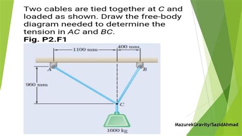
Table of Contents
- Two Cables Are Tied Together At C
- Table of Contents
- Two Cables Tied Together at C: A Comprehensive Analysis of Static Equilibrium
- Understanding Static Equilibrium
- Analyzing the Forces at Point C
- Resolving Forces into Components
- Solving for Unknown Tensions
- Three-Dimensional Analysis
- Practical Applications
- Influence of Cable Material and Geometry
- Dealing with Multiple Cables
- Considering Friction
- Advanced Analysis Techniques
- Conclusion
- Latest Posts
- Latest Posts
- Related Post
Two Cables Tied Together at C: A Comprehensive Analysis of Static Equilibrium
This article delves into the physics and engineering principles governing a system where two cables are tied together at a point, often denoted as point C. We'll explore the forces acting on this point, how to analyze the system using vector mechanics, and the practical applications of this fundamental concept in structural engineering and other fields. Understanding this scenario is crucial for designing safe and stable structures. We will cover various scenarios, including different angles of the cables, different tensions, and the impact of external forces.
Understanding Static Equilibrium
Before diving into the specifics of two cables tied together, let's establish a firm understanding of static equilibrium. In physics, an object is said to be in static equilibrium when it is at rest and the net force acting upon it is zero. This means that all forces acting on the object are balanced. This principle is fundamental to analyzing any structural system, including our scenario of two cables meeting at a point.
For an object to be in static equilibrium, two conditions must be met:
- The sum of all forces acting on the object must be zero: This is expressed mathematically as ΣF = 0. This means the vector sum of all forces is a zero vector.
- The sum of all moments (torques) acting on the object must be zero: This is expressed mathematically as ΣM = 0. This ensures the object doesn't rotate.
These conditions are crucial for ensuring the stability and safety of structures. If these conditions are not met, the structure will experience either translational motion (movement) or rotational motion (spinning), potentially leading to collapse.
Analyzing the Forces at Point C
Let's consider two cables, labeled Cable A and Cable B, tied together at point C. Each cable exerts a tension force on point C. These forces are vectors, meaning they have both magnitude (representing the tension) and direction. We can represent these forces as follows:
- T<sub>A</sub>: The tension force exerted by Cable A on point C.
- T<sub>B</sub>: The tension force exerted by Cable B on point C.
If an external load (weight or force) is applied at point C, we must also consider this force in our analysis. Let's represent this external load as F<sub>ext</sub>.
To ensure static equilibrium at point C, the vector sum of all these forces must be zero:
T<sub>A</sub> + T<sub>B</sub> + F<sub>ext</sub> = 0
This equation represents three equations—one for each direction (x, y, z)—allowing us to solve for unknown tensions or external forces. The specific equations depend on the angles of the cables and the direction of the external force.
Resolving Forces into Components
To solve the equilibrium equations, we need to resolve the tension forces into their x and y components. Let's assume a two-dimensional scenario (the cables lie in a single plane). We can define the angles of the cables with respect to a chosen coordinate system.
- θ<sub>A</sub>: The angle Cable A makes with the horizontal axis.
- θ<sub>B</sub>: The angle Cable B makes with the horizontal axis.
Now, we can resolve the tension forces into their components:
- T<sub>Ax</sub> = T<sub>A</sub> cos(θ<sub>A</sub>) (horizontal component of T<sub>A</sub>)
- T<sub>Ay</sub> = T<sub>A</sub> sin(θ<sub>A</sub>) (vertical component of T<sub>A</sub>)
- T<sub>Bx</sub> = T<sub>B</sub> cos(θ<sub>B</sub>) (horizontal component of T<sub>B</sub>)
- T<sub>By</sub> = T<sub>B</sub> sin(θ<sub>B</sub>) (vertical component of T<sub>B</sub>)
Similarly, we can resolve the external force F<sub>ext</sub> into its x and y components: F<sub>extx</sub> and F<sub>exty</sub>.
Solving for Unknown Tensions
With the forces resolved into their components, we can write the equilibrium equations:
- ΣF<sub>x</sub> = T<sub>Ax</sub> + T<sub>Bx</sub> + F<sub>extx</sub> = 0
- ΣF<sub>y</sub> = T<sub>Ay</sub> + T<sub>By</sub> + F<sub>exty</sub> = 0
These two equations allow us to solve for unknown tensions (T<sub>A</sub> and T<sub>B</sub>) or the components of the external force, provided we know the angles (θ<sub>A</sub> and θ<sub>B</sub>) and at least one tension or force component. This usually involves solving a system of simultaneous equations.
Three-Dimensional Analysis
The principles remain the same for a three-dimensional analysis. However, we need to consider three components for each force (x, y, and z). This results in three equilibrium equations:
- ΣF<sub>x</sub> = 0
- ΣF<sub>y</sub> = 0
- ΣF<sub>z</sub> = 0
Solving these equations often requires more sophisticated techniques, potentially involving matrix algebra.
Practical Applications
The analysis of two cables tied together at a point has numerous practical applications in various engineering disciplines:
- Structural Engineering: Analyzing tension in suspension bridges, cable-stayed bridges, and guy wires. Understanding the forces acting on connection points is crucial for designing safe and stable structures.
- Mechanical Engineering: Analyzing forces in cable-driven robots, tension mechanisms, and various lifting systems.
- Civil Engineering: Designing support systems for power lines, antennas, and other structures requiring cable support.
Influence of Cable Material and Geometry
The analysis presented so far assumes ideal cables – perfectly flexible and inextensible. In reality, cables possess some stiffness and may stretch under load. These factors can influence the distribution of forces and require more complex analysis techniques, often involving material properties (Young's Modulus) and cable geometry.
Furthermore, the connection point C itself introduces some complexity. The nature of the connection (e.g., a simple knot, a clevis pin, or a more sophisticated joint) affects the force distribution and the potential for failure. A more robust connection can better handle high tensions.
Dealing with Multiple Cables
The principles extend to scenarios with more than two cables tied together. In these instances, the equilibrium equations become more complex, but the fundamental approach remains consistent: resolve all forces into components, apply the equilibrium equations (ΣF = 0 and ΣM = 0), and solve for the unknown tensions or forces.
Considering Friction
In some real-world situations, friction at the connection point C can play a significant role. If the cables are wrapped around a pulley or other component, frictional forces must be incorporated into the analysis. This adds another layer of complexity to the calculations, requiring the use of friction coefficients and potentially iterative solution methods.
Advanced Analysis Techniques
For highly complex scenarios involving many cables, non-linear cable behavior, or dynamic loading, advanced analysis techniques might be necessary. These could include:
- Finite Element Analysis (FEA): This powerful computational method can accurately model the behavior of complex cable systems, taking into account material properties, geometry, and loading conditions.
- Numerical methods: Iterative techniques such as Newton-Raphson methods can be used to solve complex systems of non-linear equations arising from the analysis.
Conclusion
Analyzing the forces at a point where two cables are tied together is a fundamental problem in engineering mechanics. Understanding the principles of static equilibrium, resolving forces into components, and solving the resulting equations is crucial for designing safe and efficient structures and systems. While this article focused on the basic principles, real-world applications may involve additional complexities requiring advanced analytical methods. However, mastering the fundamental concepts presented here provides a solid foundation for tackling these more challenging scenarios. Remember to always consider the influence of cable materials, geometry, connections, friction and potential advanced analysis techniques for accurate and safe design.
Latest Posts
Latest Posts
-
People With Lighter Colored Hair Have Melanin In The
Apr 01, 2025
-
Pn Mental Health Online Practice 2023 A
Apr 01, 2025
-
What Is Cold And Comes In Cans
Apr 01, 2025
-
Which Of The Following Is A Structural Isomer To Glucose
Apr 01, 2025
-
Hypoxemia Can Be Evidenced On Physical Exam As
Apr 01, 2025
Related Post
Thank you for visiting our website which covers about Two Cables Are Tied Together At C . We hope the information provided has been useful to you. Feel free to contact us if you have any questions or need further assistance. See you next time and don't miss to bookmark.
