For The Beam And Loading Shown
Holbox
Mar 21, 2025 · 7 min read
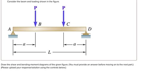
Table of Contents
For the Beam and Loading Shown: A Comprehensive Guide to Analysis and Design
Determining the behavior of beams under various loading conditions is fundamental to structural engineering. This article delves into the analysis and design considerations for beams subjected to different types of loads, offering a comprehensive understanding of the principles involved. We'll explore various methods for calculating reactions, shear forces, bending moments, and deflections, ultimately providing the knowledge necessary to ensure structural integrity and safety.
Understanding Beam Types and Loading Conditions
Before diving into the analysis, let's clarify the different types of beams and loads encountered in structural engineering.
Types of Beams:
-
Simply Supported Beams: These beams are supported at both ends, allowing rotation but preventing vertical movement. They are the most common type and relatively straightforward to analyze.
-
Cantilever Beams: Fixed at one end and free at the other, cantilever beams are often used for balconies or overhanging structures. Their analysis involves considering the fixed end's reaction forces and moments.
-
Overhanging Beams: These beams extend beyond their supports, leading to more complex loading conditions. The overhanging portions introduce additional moments and shear forces.
-
Continuous Beams: These beams rest on more than two supports, resulting in continuous spans. Their analysis requires considering the interaction between adjacent spans.
-
Fixed Beams: Fixed at both ends, preventing both rotation and vertical movement, these beams are highly constrained and typically exhibit higher stresses.
Types of Loads:
-
Concentrated Loads: These are point loads applied at a specific location on the beam. They are often represented by a single force acting at a point.
-
Uniformly Distributed Loads (UDL): These loads are evenly distributed along the length of the beam, such as the weight of a concrete slab. They are represented by a force per unit length (e.g., kN/m or lb/ft).
-
Uniformly Varying Loads (UVL): These loads increase or decrease linearly along the beam's length. Examples include the pressure of a triangularly distributed soil load.
-
Moment Loads: These loads apply a bending moment at a specific point on the beam.
Analyzing Beams: Determining Reactions, Shear Forces, and Bending Moments
The analysis of beams involves determining the reactions at the supports, shear forces, and bending moments along the beam's length. These calculations are crucial for assessing stresses and deflections.
Determining Reactions:
The first step in beam analysis is calculating the reactions at the supports. This is done using equilibrium equations:
- ΣFx = 0: The sum of horizontal forces is zero.
- ΣFy = 0: The sum of vertical forces is zero.
- ΣM = 0: The sum of moments about any point is zero.
The number of unknowns (reactions) equals the number of equilibrium equations available. For simply supported beams, there are typically two vertical reactions. For cantilever beams, there's a vertical reaction and a moment reaction at the fixed end. More complex beams require more elaborate analysis.
Shear Force Diagrams (SFD):
A shear force diagram graphically represents the shear force at each point along the beam's length. To construct an SFD:
- Calculate reactions: Determine the support reactions as described above.
- Section the beam: Imagine cutting the beam at various points.
- Draw free body diagrams: For each section, draw a free body diagram showing the forces and reactions acting on that section.
- Calculate shear force: The shear force at any point is the algebraic sum of the vertical forces acting on either side of the section.
- Plot the shear force: Plot the calculated shear forces against their respective positions along the beam's length. Points of zero shear force are significant.
Bending Moment Diagrams (BMD):
A bending moment diagram graphically represents the bending moment at each point along the beam's length. To construct a BMD:
- Calculate reactions: Determine the support reactions.
- Section the beam: Similar to the SFD, section the beam at various points.
- Draw free body diagrams: For each section, draw a free body diagram.
- Calculate bending moment: The bending moment at any point is the algebraic sum of the moments of all forces acting on one side of the section. Consider the sign convention (clockwise moments are usually positive).
- Plot the bending moment: Plot the calculated bending moments against their respective positions. Points of maximum bending moment are critical for design.
Methods of Analysis:
Several methods exist for analyzing beams and determining shear forces and bending moments. These include:
-
Method of Sections: This method involves cutting the beam at various points and analyzing the equilibrium of the resulting sections.
-
Method of Joints: While primarily used for trusses, this method can be adapted for some beam types.
-
Influence Lines: Influence lines show the variation in shear force or bending moment at a specific point on the beam as a unit load moves along the beam's length. This is useful for live loads.
-
Superposition: This method allows combining the effects of multiple loads by analyzing each load individually and then summing the results. This is valid for linear elastic systems.
-
Software-based analysis: Sophisticated software packages (e.g., finite element analysis software) can be used for complex beam analyses, particularly for irregular geometries or non-linear material behavior.
Determining Beam Deflections:
Deflection is the vertical displacement of the beam under load. Excessive deflection can affect the functionality and aesthetics of a structure. Common methods for calculating deflection include:
-
Double Integration Method: This method involves integrating the bending moment equation twice to obtain the deflection equation. Boundary conditions are then applied to determine the constants of integration.
-
Moment-Area Method: This method uses the area under the bending moment diagram to determine deflection. It's particularly useful for beams with complex loading.
-
Conjugate Beam Method: This method transforms the original beam into a "conjugate" beam with modified properties and loading. The deflection of the original beam can then be found by analyzing the conjugate beam.
-
Superposition (for deflection): Similar to the bending moment analysis, superposition can be applied for calculating deflection caused by multiple loads.
-
Software-based methods: Finite element analysis software provides accurate deflection calculations for complex beam geometries and loading conditions.
Beam Design Considerations:
Once the analysis is complete, the design process begins. This involves selecting an appropriate beam section that can withstand the calculated stresses and deflections. Key considerations include:
-
Material Selection: Choosing the appropriate material (e.g., steel, timber, reinforced concrete) based on strength, stiffness, cost, and durability.
-
Section Selection: Selecting a beam section (e.g., rectangular, I-beam, T-beam) that satisfies strength and stiffness requirements. The section modulus (S) is a crucial parameter.
-
Stress Checks: Checking for bending stresses (σ = M/S), shear stresses, and deflection to ensure they remain within allowable limits. These limits are governed by building codes and material properties.
-
Safety Factors: Applying appropriate safety factors to account for uncertainties in material properties, loading conditions, and analysis assumptions.
-
Deflection Limits: Ensuring that deflections remain within acceptable limits to prevent damage or aesthetic issues. Deflection limits are specified in building codes.
Illustrative Example: A Simply Supported Beam with a Central Point Load
Consider a simply supported beam of length L, carrying a central point load P.
-
Reactions: The reactions at each support are P/2.
-
SFD: The shear force is P/2 from the left support to the center, then -P/2 from the center to the right support. The SFD is a stepped diagram.
-
BMD: The bending moment is zero at the supports and maximum at the center, with a value of PL/4. The BMD is triangular.
-
Deflection: The maximum deflection at the center can be calculated using standard formulas: δmax = PL³/48EI, where E is the modulus of elasticity and I is the moment of inertia of the beam section.
Conclusion:
Analyzing and designing beams under various loading conditions is crucial for ensuring structural safety and functionality. A thorough understanding of beam types, loading conditions, analysis methods, and design considerations is essential for structural engineers. This article provides a comprehensive overview of these principles, equipping you with the knowledge to approach beam analysis and design confidently and accurately. Remember to consult relevant building codes and standards for specific design requirements and safety factors. Using software tools can significantly enhance the efficiency and accuracy of complex beam analyses. Always prioritize safety and adhere to best practices in structural engineering.
Latest Posts
Latest Posts
-
Transpose The Data In Range I3
Mar 22, 2025
-
What Characterizes Depolarization The First Phase Of The Action Potential
Mar 22, 2025
-
How Many C Atoms Are In 5 50 G Of C
Mar 22, 2025
-
Why Is Controlling The Output Of Generative Ai Systems Important
Mar 22, 2025
-
Cross Functional Self Managed Teams Work Best When
Mar 22, 2025
Related Post
Thank you for visiting our website which covers about For The Beam And Loading Shown . We hope the information provided has been useful to you. Feel free to contact us if you have any questions or need further assistance. See you next time and don't miss to bookmark.
