Consider The Circuit Diagram In The Figure
Holbox
Mar 27, 2025 · 7 min read
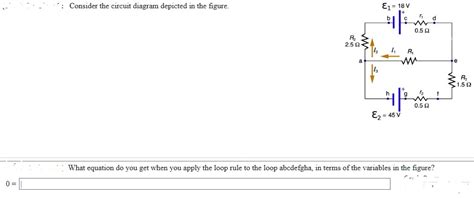
Table of Contents
- Consider The Circuit Diagram In The Figure
- Table of Contents
- Decoding Circuit Diagrams: A Comprehensive Guide
- Understanding the Basics: Components and Symbols
- Analyzing Simple Circuits: Series and Parallel Configurations
- Advanced Circuit Analysis Techniques
- Practical Applications and Examples
- Beyond the Basics: Advanced Topics
- Conclusion: Mastering Circuit Diagrams
- Latest Posts
- Latest Posts
- Related Post
Decoding Circuit Diagrams: A Comprehensive Guide
Analyzing circuit diagrams is fundamental to understanding how electrical and electronic systems work. This article delves deep into the interpretation and analysis of circuit diagrams, providing a comprehensive guide for beginners and experienced enthusiasts alike. While we won't be referencing a specific "figure" as requested (as providing that would require image embedding capabilities beyond this text-based format), the principles discussed here are universally applicable to any circuit diagram you encounter. We will cover fundamental components, common symbols, analysis techniques, and practical applications.
Understanding the Basics: Components and Symbols
Before diving into complex diagrams, let's establish a strong foundation. Circuit diagrams use standardized symbols to represent various electronic components. Knowing these symbols is the first step towards effective analysis.
1. Power Sources: These are represented by various symbols, depending on the type of source:
- DC Power Source (Battery): Typically shown as a long line (positive terminal) and a short line (negative terminal). The voltage is often indicated next to the symbol.
- AC Power Source: Represented by a circle with a sinusoidal waveform inside, indicating alternating current. The voltage and frequency are often indicated.
2. Resistors: These passive components limit the flow of current. Their symbol is a zig-zag line, and the resistance value (in ohms) is typically written next to it.
3. Capacitors: These components store electrical energy. They are represented by two parallel lines, sometimes with curved ends. The capacitance value (in farads) is generally included.
4. Inductors: These components store energy in a magnetic field. They are represented by a coil or spiral shape. The inductance value (in henries) is usually specified.
5. Diodes: These are one-way electrical valves, allowing current to flow in only one direction. The symbol resembles an arrow pointing to a line, indicating the direction of current flow.
6. Transistors: These are active components that can amplify or switch electronic signals. There are several types (Bipolar Junction Transistors (BJTs), Field-Effect Transistors (FETs)), each with its unique symbol. The symbol typically includes the emitter, base, and collector (for BJTs) or source, gate, and drain (for FETs).
7. Integrated Circuits (ICs): These contain numerous transistors and other components within a single package. They are represented by a rectangular shape with the IC's name and number inside.
8. Wires and Connections: Wires connecting different components are usually represented by straight lines. Junctions or connections are shown with a dot where wires meet.
Analyzing Simple Circuits: Series and Parallel Configurations
Once you're familiar with the symbols, you can start analyzing simple circuit configurations. Two fundamental configurations are series and parallel circuits:
1. Series Circuits: In a series circuit, components are connected end-to-end, forming a single path for current to flow. The key characteristics of a series circuit are:
- Total Resistance: The total resistance is the sum of individual resistances (R<sub>total</sub> = R<sub>1</sub> + R<sub>2</sub> + R<sub>3</sub> + ...).
- Current: The current is the same throughout the entire circuit.
- Voltage: The voltage across each component is proportional to its resistance (Ohm's Law: V = IR).
2. Parallel Circuits: In a parallel circuit, components are connected across each other, providing multiple paths for current to flow. The key characteristics of a parallel circuit are:
- Total Resistance: The reciprocal of the total resistance is the sum of the reciprocals of individual resistances (1/R<sub>total</sub> = 1/R<sub>1</sub> + 1/R<sub>2</sub> + 1/R<sub>3</sub> + ...).
- Current: The total current is the sum of the currents through each branch.
- Voltage: The voltage across each component is the same.
Understanding these basic relationships allows you to calculate voltage, current, and resistance in simple circuits using Ohm's Law and Kirchhoff's Laws.
Advanced Circuit Analysis Techniques
Analyzing more complex circuits requires advanced techniques beyond simple series and parallel combinations:
1. Kirchhoff's Laws: These are fundamental laws governing circuit analysis:
- Kirchhoff's Current Law (KCL): The sum of currents entering a node (junction) equals the sum of currents leaving the node.
- Kirchhoff's Voltage Law (KVL): The sum of voltages around any closed loop in a circuit is zero.
2. Mesh Analysis: This method uses KVL to solve for currents in a circuit by setting up equations for each mesh (loop) in the circuit.
3. Nodal Analysis: This method uses KCL to solve for voltages at each node in a circuit.
4. Thevenin's Theorem: This simplifies complex circuits by replacing a portion of the circuit with an equivalent voltage source and series resistance.
5. Norton's Theorem: This is a dual of Thevenin's Theorem, replacing a portion of the circuit with an equivalent current source and parallel resistance.
These techniques are crucial for analyzing complex circuits with multiple sources, components, and loops. Many software tools are available to aid in the analysis and simulation of such circuits.
Practical Applications and Examples
Circuit diagrams are essential tools across numerous fields:
1. Electronics Design: Engineers use circuit diagrams to design and build everything from simple electronic gadgets to complex computer systems. They allow for planning, simulation, and debugging before physical construction.
2. Troubleshooting and Repair: Technicians use circuit diagrams to diagnose problems in malfunctioning electronic devices. By tracing the paths of signals and power, they can pinpoint faulty components.
3. Education and Training: Circuit diagrams are fundamental to learning electronics. They provide a visual representation of how components interact and function within a system.
4. Automotive Systems: Modern vehicles rely heavily on electronic control units (ECUs) governed by complex circuits. Understanding these circuits is essential for automotive technicians and engineers.
5. Robotics and Automation: Robots and automated systems employ intricate circuits to control motors, sensors, and other components. Circuit diagrams are used in their design, programming, and maintenance.
Let's consider some illustrative examples (without specific diagrams, focusing on conceptual understanding):
-
A simple light switch circuit: This involves a power source, a switch, and a light bulb connected in series. Analyzing this reveals how the switch controls the flow of current to the bulb.
-
A voltage divider circuit: This uses two resistors connected in series to divide a voltage into smaller voltages. Analyzing this illustrates how voltage can be controlled using passive components.
-
A simple amplifier circuit: This could involve a transistor, resistors, and capacitors to amplify a weak signal. Analyzing this shows how active components can boost signal strength.
-
A digital logic circuit: This might involve logic gates (AND, OR, NOT) connected to perform Boolean operations. Analyzing this demonstrates the principles of digital electronics.
Beyond the Basics: Advanced Topics
The world of circuit diagrams extends beyond the basic components and analysis techniques mentioned above. Advanced topics include:
-
Frequency Response Analysis: This examines how a circuit's behavior changes with varying frequencies of input signals. This is crucial in areas like audio and radio frequency systems.
-
Transient Analysis: This involves examining how a circuit behaves when subjected to sudden changes in input signals. This is essential for understanding the circuit's response to switching events.
-
Simulation Software: Software such as LTSpice, Multisim, and others provide powerful tools for simulating circuit behavior and verifying designs before physical implementation.
-
Signal Integrity: This addresses the quality of signals as they travel through a circuit, considering issues like reflections, noise, and crosstalk. This is increasingly important in high-speed digital systems.
Conclusion: Mastering Circuit Diagrams
Mastering the ability to read and interpret circuit diagrams is a crucial skill in electronics and related fields. It enables you to understand how electronic systems function, troubleshoot problems, and design new systems. By thoroughly understanding fundamental components, analysis techniques, and practical applications, you can unlock a world of possibilities in the realm of electronics. Remember that consistent practice and exposure to diverse circuit diagrams are vital to building your expertise in this essential area.
Latest Posts
Latest Posts
-
How Do You Cite A Syllabus In Apa
Mar 30, 2025
-
Who Should Participate In Basic Emergency Preparedness Training And Drills
Mar 30, 2025
-
What Is One Distinct Feature Of Determinate Plants That Differentiates
Mar 30, 2025
-
Select The Correct Statement Below The National Response Framework
Mar 30, 2025
-
Asp Provided Amnesty Collection Points Are Available
Mar 30, 2025
Related Post
Thank you for visiting our website which covers about Consider The Circuit Diagram In The Figure . We hope the information provided has been useful to you. Feel free to contact us if you have any questions or need further assistance. See you next time and don't miss to bookmark.
