A Cantilever Wood Beam Consits Of Eight 2 In
Holbox
Mar 12, 2025 · 5 min read
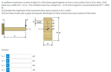
Table of Contents
Analyzing an Eight-Piece 2x Cantilever Wood Beam: Design, Strength, and Failure Modes
Understanding the structural behavior of cantilever beams is crucial in various engineering applications, from simple shelving units to complex building structures. This article delves deep into the analysis of a cantilever wood beam composed of eight 2-inch pieces, exploring its design considerations, strength calculations, potential failure modes, and optimization strategies. We'll utilize fundamental engineering principles and provide practical insights for readers interested in structural design and analysis.
Understanding Cantilever Beams
A cantilever beam is a structural element that is fixed at one end and free at the other. This configuration makes it particularly susceptible to bending stresses under load. The load applied to the free end generates bending moments and shear forces throughout the beam's length, which must be carefully considered during design to prevent failure.
Stress and Strain in a Cantilever Beam
When a load is applied to a cantilever beam, it experiences both bending stress and shear stress. Bending stress is the internal stress resulting from the bending moment, causing compression on one side of the beam and tension on the other. Shear stress is the internal stress resulting from the shear force, causing the beam to resist sliding along its cross-section.
Factors Affecting Beam Strength
Several factors influence the strength of a cantilever beam:
-
Material Properties: The type of wood significantly impacts its strength. Different species possess varying strength-to-weight ratios, modulus of elasticity (E), and allowable stress values. Understanding these properties is crucial for accurate calculations.
-
Cross-sectional Area: A larger cross-sectional area increases the beam's resistance to bending and shear stresses. The shape of the cross-section also matters; a wider, deeper beam is generally stronger.
-
Length of the Beam: The longer the beam, the greater the bending moment and shear force at the fixed end, reducing overall strength and increasing the risk of failure.
-
Type of Load: Concentrated loads (applied at a single point) induce higher stresses than uniformly distributed loads (spread evenly across the length).
-
Deflection: Excessive deflection (bending of the beam under load) can be detrimental, affecting functionality and aesthetics. Allowable deflection limits must be considered during the design phase.
Analyzing the Eight-Piece 2x Cantilever Wood Beam
Let's consider a cantilever wood beam constructed from eight pieces of 2-inch lumber. We'll assume they are arranged in a single layer to maximize the cross-sectional area. To perform a thorough analysis, we must define the following:
-
Type of Wood: Specify the wood species. Different species have varying strength properties. We'll assume a commonly used species like Douglas Fir for this example.
-
Dimensions: We're given 2-inch lumber. The actual dimensions will be slightly smaller due to manufacturing tolerances. Let's assume the actual dimensions are 1.5 inches x 1.5 inches for simplicity. A total cross-section of 12 inches x 1.5 inches is obtained with 8 pieces.
-
Length: The length of the cantilever beam dictates the bending moment and shear force. Let's assume a length of 8 feet (96 inches).
-
Load: Define the type and magnitude of the load. Let's consider a concentrated load at the free end of the beam.
Calculating Bending Moment and Shear Force
The maximum bending moment for a cantilever beam with a concentrated load (P) at the free end is:
M<sub>max</sub> = P * L
Where:
- M<sub>max</sub> is the maximum bending moment
- P is the concentrated load
- L is the length of the beam
The maximum shear force is equal to the concentrated load:
V<sub>max</sub> = P
Calculating Bending Stress
Bending stress (σ) can be calculated using the flexure formula:
σ = M * c / I
Where:
- σ is the bending stress
- M is the bending moment
- c is the distance from the neutral axis to the outermost fiber (half the height of the beam)
- I is the moment of inertia of the cross-section
Calculating Shear Stress
Shear stress (τ) can be calculated using:
τ = V * Q / (I * b)
Where:
- τ is the shear stress
- V is the shear force
- Q is the first moment of area
- I is the moment of inertia
- b is the width of the beam
Determining Allowable Stress
The allowable stress for the chosen wood species must be obtained from relevant design codes and standards. These codes provide safety factors to ensure the structural integrity of the beam under load.
Failure Modes
Several failure modes can occur in a cantilever wood beam:
-
Yielding: The wood fibers exceed their elastic limit, resulting in permanent deformation.
-
Fracture: The wood fibers break under excessive stress.
-
Buckling: The beam buckles laterally under compressive stresses.
-
Shear Failure: The beam fails due to excessive shear stress.
-
Compression Failure: The beam fails in compression at the fixed end under high bending moments.
-
Tension Failure: The beam fails in tension at the free end.
Optimizing the Beam Design
Several strategies can be used to optimize the eight-piece 2x cantilever wood beam design:
-
Increasing Cross-Sectional Area: Adding more 2x lumber pieces or using thicker pieces will increase the beam's strength and stiffness.
-
Changing Beam Configuration: Experiment with different arrangements of the lumber pieces to optimize moment of inertia and resistance to bending. Lamination or gluing multiple layers together could improve overall strength.
-
Using Stronger Wood Species: Selecting a wood species with a higher modulus of elasticity and allowable stress will significantly enhance the beam's strength and stiffness.
-
Reducing Beam Length: A shorter beam experiences lower bending moments and shear forces, improving its load-carrying capacity.
-
Adding Support: Incorporating intermediate supports can significantly reduce bending moments and shear forces.
Conclusion
Analyzing the strength and stability of a cantilever wood beam requires careful consideration of material properties, loading conditions, and potential failure modes. This article provides a framework for analyzing an eight-piece 2x cantilever wood beam, highlighting crucial parameters and calculation methods. Remember to always consult relevant design codes and standards, use appropriate safety factors, and consider potential failure mechanisms to ensure the structural integrity and safety of any wooden structure. The specific calculations and optimization strategies will depend on the exact specifications of the beam and the applied load. This detailed analysis allows for a more informed design process, reducing the risk of structural failure and enhancing the overall performance of the cantilever beam. Through careful design and analysis, a robust and efficient cantilever wood beam can be created for various applications.
Latest Posts
Latest Posts
-
How To Delete A Chegg Question
Mar 12, 2025
-
How To Delete Payment Method On Chegg
Mar 12, 2025
-
Cats And Dogs Passage Teas Test Chegg
Mar 12, 2025
-
How To Delete A Question From Chegg
Mar 12, 2025
-
Evaporation And Intermolecular Forces Lab Chegg
Mar 12, 2025
Related Post
Thank you for visiting our website which covers about A Cantilever Wood Beam Consits Of Eight 2 In . We hope the information provided has been useful to you. Feel free to contact us if you have any questions or need further assistance. See you next time and don't miss to bookmark.
